
Saint-Gobain SEVA
SIAE 2025

SAINT-GOBAIN SEVA’S KNOW-HOW FOR DESIGNING AND BUILDING EFFICIENT HF & SPF TITANIUM FORMING TOOLS
Saint-Gobain SEVA’s “Alloys & Transformation” industrial Business Unit includes a specialized foundry and a wide range of machining capabilities. Thanks to these industrial capabilities and our expertise in designing and building special tooling for high-temperature environments, we entered the aircraft industry several years ago. We supply Hot-Forming & Super-Plastic-Forming toolings as a first-tier and second-tier supplier. SEVA offers a complete service, coordinating and performing most of the steps internally to design and build such tooling.
STEPS TO BUILD HF & SPF TITANIUM FORMING TOOLS
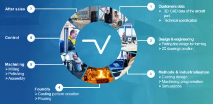
Here are detailed the various steps we need to go through to create HF or SPF tooling: Everything starts with the customer’s data and technical specifications, which define the customer’s needs for the tooling and its conditions of use. Based on the aircraft part design, our design office will study the corresponding tooling design for both the casting and realization phases. The project will then proceed through a methods and industrialization phase to precisely define the parameters for each production step. In most cases, we will also conduct required simulations (for both the casting and machining phases) to minimize any risks. Next is the casting phase itself, which involves designing and creating the pattern, creating the mold, preparing the alloy, pouring, and unmolding the as-cast tooling to be sent for machining (after possible heat treatment depending on the grade). During the machining phase, the tooling will be: Milled to achieve the finished shapes and dimensions, Polished to obtain the required surface quality for efficient forming processing. Then, the accessories are added, and the tooling undergoes a final check and customer reception before shipment.
CUSTOMER’S DATAS
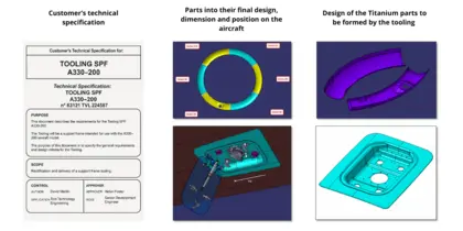
Everything starts with the customer’s data and technical specifications, where the customer precisely defines the part’s design, its position on the aircraft, and the requirements for the tooling itself, as well as its conditions of use, which are crucial to be considered. Of course, if it is just to duplicate an existing tooling, we can rely on the complete tooling file provided by the customer. However, the customer’s data, technical specifications, and conditions of use become even more critical when creating a completely new tooling. This includes starting from the aircraft part design and designing the corresponding tool by taking all relevant parameters into account. Depending on the level of details provided, we will speak of a “Build to print” or a “Build to spec.” project…
DESIGN & ENGINEERING
Customer datas and specification analysis
- Tooling technical specification
- Press technical specification
- Aircraft part balanced into its forming position (analysis and suppression of the possible undercuts)
Design, dimensioning
- Defining the parting line
- General volume and tooling design
- Positioning the tooling functionalities
- Centering accessories
- Event holes network,
- Thermocouple …
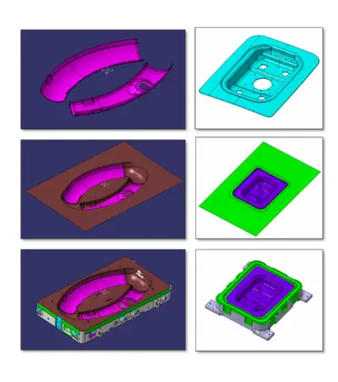
During the design phase, after receiving the 3D CAD data from the customer, our design office will need to:
Check the part balancing within the tooling to ensure it can be unmolded without deformation after the SPF process. If any draft angles are discovered, rebalancing the part within the tooling (or even redesigning it) may be necessary. This point must be discussed with the customer.
Define the parting lines: This is the surface that connects the aircraft part to be formed with the general tooling design. The parting line must also be validated by the customer (possibly through a forming simulation) to ensure the most efficient forming process.
Once the parting-line surfaces are created, the general tooling design can begin, taking into account:
Customer specifications and conditions of use: This includes press specifications, forming process parameters, the relative homothety between the tooling and the titanium part (as they do not have the same expansion coefficients), the target yield depending on the number of parts to be produced, and the titanium sheets throughput.
Tooling production parameters such as:
Casting parameters: Total weight of the tooling, required homogeneity of wall thicknesses, tooling handling, etc.
Machining parameters: Accessibility of cutting tools, minimum radius, etc.
DESIGN & ENGINEERING
- 2D drawing creation for the production
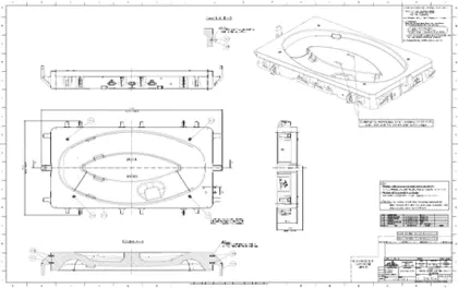
- Tooling 3D CAD Data
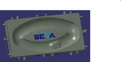
Finally, the 2D drawings will also be created and validated with the customer. They will be used as references for realization and controls.
FOUNDRY METHODS
Feeding Feeder Solidification
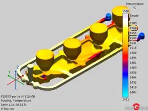
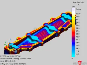
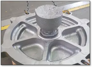
Next comes the casting study itself, including simulations. This is an absolutely essential step before launching the complete casting process. The foundry methods department will design the tooling casting process by adjusting and optimizing several parameters such as:
Tooling design: This includes the tooling’s radius, surface thicknesses and possible addition of structural reinforcements.
Casting yield: The ratio between the weight of liquid metal used and the weight of the obtained raw casting.
Dimensions and design of casting auxiliaries: This includes the “feeders,” which are liquid metal reserves added to the mold to compensate for metal shrinkage during solidification. Feeders help prevent internal defects in the cast part by avoiding shrinkage porosities and locating them in the feeders instead of the tooling.
The tooling design will be optimized and validated through various successive steps of simulations (using MagmaSoft software or other) until the best simulation results are achieved for:
Feeding : This allows validation of the general tooling design.
Solidification: This defines and confirms the optimal sizing of feeders and checks the metal behavior during solidification.
Finally, based on the defined tooling design, the corresponding pattern will be designed and built. This pattern will then be used to create the sand mold in which the liquid metal will be poured to cast the required tooling.
As you can see, these are dynamic and multiphysical simulations (including material flow, physical, chemical and thermal behavior according to the time).
Such simulations are quite complexe. Based on industry specific software, they are progressively made more and more efficient and reliable by defining our own parameters and enriching our own database with values adapted to our alloys based on our observations.
VARIOUS TYPES OF ALLOY GRADES AND COMPOSITIONS & ALLOYS FOR HF ALLOYS FOR SPF
Comparison of the main components ratios included into the HF & SPF toolings
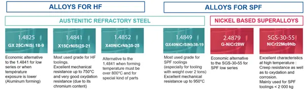
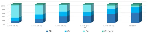
During this phase, an important parameter to consider in the tooling design (and to discuss with the customer) is the choice of alloy grade. Several possible grades for casting tooling exist, but they do not all have the same characteristics or performance. Here again, some compromises may need to be made.
For hot-forming, austenitic refractory steels are most frequently used.
However, SPF processing at higher temperatures, more advanced materials such as Nickel-based superalloys are required.
Finally, in special cases, we even already used some of our in-house Cobalt-based alloys which are even more resistant (more in particular considering creep resistance at higher temperatures) and which could even be an opportunity for future hybrid HF-SPF process ?
As we can see in the graph above comparing each grade’s composition, the Nickel content primarily drives the alloy’s thermal performance, but it also affects the final price of the tooling.
ALLOYS MECHANICAL CHARACTERISTICS COMPARISON
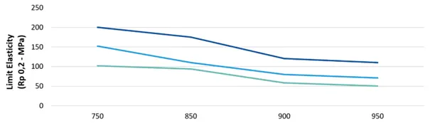

The Nickel content also influences the mechanical characteristics at high temperatures. So, based on our experience, the choice of the alloy grade the tooling will be made of is a very important step, not to be negliged and to be discussed with the customer. Also considering its conditions of use, this will greatly impact the tooling lifetime.
MACHINING METHODS
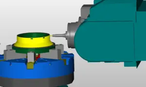
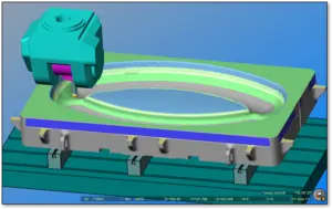
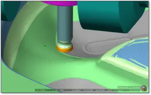
CNC programming and simulation before machining
Next is the methods phase for the machining operations. This includes programming the cutting tool paths (CNC) and simulations, as well as creating all the necessary documentation for the machine to guide the operators and the instructions about the machining sequence. This documentation will define the cutting tools to be used and all other machining parameters, such as cutting speed and successive steps. For HF & SPF forming tools, we consider simulation to be absolutely mandatory to ensure the tooling is machined under optimal conditions.
All tooling shapes are programmed and simulated to check the cutting tool paths, especially for deep shapes, to avoid any interference between the workpiece and the cutting tool. This process helps detect and avoid any programming bugs and allows us to define the best compromise in terms of cutting-tool paths, aiming for the best balance between achieving optimal crest heights from machining and minimizing the need for extensive polishing.
MACHINING METHODS
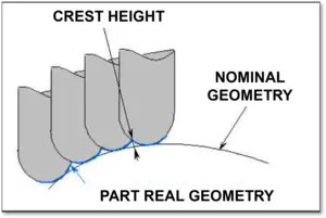
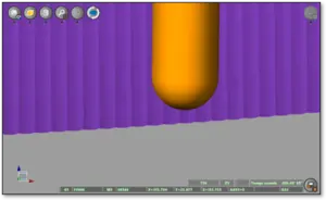
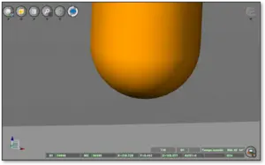
Indeed, the higher the machining crests, the faster the machining operation will be. However, this will also result in a longer polishing phase. This compromise needs to be defined during programming, depending on the surface typologies and the customer’s expectations. These choices can also significantly impact the final cost of the tooling.
CASTING PROCESS
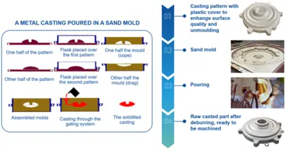
After the design and simulations, the project realization moves to the “physical” steps, starting with the various stages of the foundry process to cast the tooling:
- Creation of the foundry pattern: Most commonly made of polystyrene for tooling, as opposed to wooden patterns for serial parts.
- Sand mold creation, preparation, and clamping.
- Molten metal pouring: Using gravity casting.
- Cooling.
- Part extraction (or “shakeout”).
- Shotblasting.
- Deburring.
- Heat treatment phase, if required.
MACHINING AND POLISHING
Cutting tool used for the roughing phase
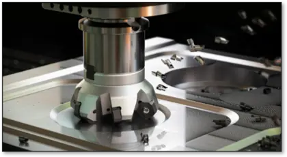
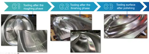
The machining phase involves giving the tooling its desired final shape by removing excess material (using cutting tools like the one shown here). After this phase, the tolerances on the molding shape can reach between +/-0.2 up to +/-0.05 mm. For SPF, the vent holes network will be judiciously placed and drilled to optimize the SPF process. Thermocouples and accessories for centering and fixation on the press will also be added. Finally, the tooling will be sent for polishing to reduce the surface roughness (Ra) from 1.6 to 0.4 on the molding shapes and parting lines.
FINAL CONTROL
The final check before shipment to the customer generally includes:
- Results about material integrity: Chemical analysis using a mass spectrometer.
- Mechanical tests as previously defined in the customer’s specifications and/or the corresponding alloy grade standard. These tests will be conducted on samples poured during the same heat as the tooling.
- Various possible non-destructive tests (NDT) performed on the tooling itself, according to the customer’s request. The main ones include:
- Liquid Penetrant Testing (LPT) according to agreed criteria previously defined. The picture here shows a white LPT without any indication, confirming the absence of any foundry defects (such as cracks, holes, or shrinkage). This criterion is extremely important for the tooling’s lifetime, which generally targets about 24 campaigns of 24 forming cycles, totaling 576 forming cycles over 2 years.
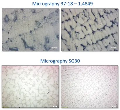
- Metallography (macrography and/or micrography): The pictures here confirm the microstructure with an austenitic matrix and a network of generally fine and rounded carbides, elongated in shape, lining the grain boundaries.
FINAL CONTROL
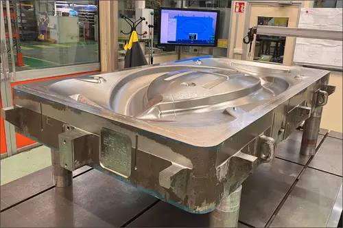
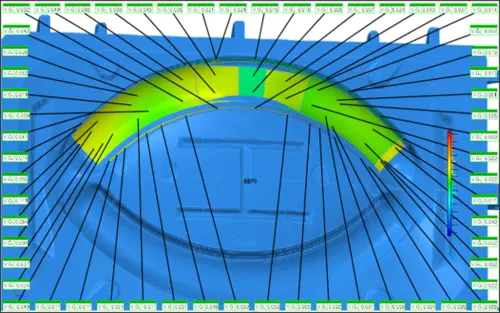
Of course, the final check will also include dimensional results, particularly focusing on the molding surfaces and the parting lines. This will be conducted using:
3D dimensional control: Utilizing contact probes or scanning.
Surface state control.
EXAMPLES
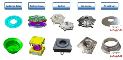
Here are shown real examples of tooling built and the different steps they went through: from customer data to the aircraft part, including tooling design, casting, and machining phases.
YOUR CONTACTS
- Florian BERNARD
Head of Sales Alloys & Transformation
Tel : +33.3.85.47.25.88 – Mob : +33.6.88.16.04.54